


dickandlois
-
Content Count
4234 -
Joined
-
Last visited
-
Days Won
12
Posts posted by dickandlois
-
-
The followling is information on how the cooling units work.
Cooling Unit (How it works)
Click here for bigger graphic (49k).
The graphic below represents a cooling unit in full operation. There's a lot to cover here, so you might consider printing this page and going to the bigger graphic to follow along. The graphic may seem a little confusing at first, because quite a few things are happening at once. But, when broken down to a section at a time, it is a fairly simple system.
Boiler. A precise heat (electric heat element or gas flame) is applied to the boiler to begin operation. Heat is transferred from the outer shell of the boiler through the weak ammonia solution to the perk tube. This style of boiler is referred to as the "new" style boiler. The "old" style boiler had the heat element holder and chimney connected directly to the perk tube, without the benefit of the outer shell to slow (not prevent) over heating in situations like being run out of level.
The perk tube is provided with a rich ammonia solution (a high percentage of ammonia to water) from the absorber tank. When heated, the ammonia in the rich ammonia solution begins to vaporize (sooner than the water would) creating bubbles and a percolating effect. The ammonia vapor pushes the now weakening solution up and out of the perk tube. The ammonia vapor (gas) leaving the perk tube goes upward towards the top of the cooling unit, passing through the rectifier. The rectifier is just a slightly cooler section of pipe that causes water that might have vaporized to condense and drop back down. The water separator at the top of the cooling unit
(only on some models) prevents any water that might have escaped the rectifier to condense and fall back. After this point, pure ammonia vapor is delivered to the condenser.
Meanwhile, back at the perk tube, the weaker solution expelled from the perk tube by the ammonia vapor drops into the weak ammonia solution surrounding the perk tube. Here, a little more ammonia vapor is generated and rises. The weak ammonia solution flows down ward and through the outer shell of the liquid heat exchanger, where heat is transferred to the rich ammonia solution on its way to the perk tube. The weak ammonia solution then flows to the top of the absorber coils and enters at a cooler temperature.
Condenser. Ammonia vapor enters the condenser where it is cooled by air passing through the metal fins of the condenser. The cooling effect of the condenser coupled with a series of step downs in pipe size forces the ammonia vapor into a liquid state, where it enters the evaporator section.
Evaporator. Liquid ammonia enters the low temperature evaporator (freezer) and trickles down the pipe, wetting the walls. Hydrogen, supplied through the inner pipe of the evaporator, passes over the wetted walls, causing the liquid ammonia to evaporate into the hydrogen atmosphere at an initial temperature of around -20º F. The evaporation of the ammonia extracts heat from the freezer. At the beginning stages, the pressure of the hydrogen is around 350 psi (pounds per square inch), while the pressure of the liquid ammonia is near 14 psi. As the ammonia evaporates and continues to trickle down the tube, its pressure and therefore its evaporation temperature rise.
The liquid ammonia entering the high temperature evaporator (refrigerator portion) is around 44 psi, while the pressure of the hydrogen has dropped to 325. Under these conditions, the evaporation temperature of the liquid ammonia is +15º F. Heat is removed from the refrigerator box through the fins attached to the high temperature evaporator. The ammonia vapor created by the evaporation of the liquid ammonia mixes with the already present hydrogen vapor, making it heavier. Since the ammonia and hydrogen vapor mixture is heavier than the purer hydrogen, it drops down through the evaporators, through the return tube to the absorber tank.
Absorber. When the ammonia and hydrogen vapor mixture enters the absorber tank through the return tube, much of the ammonia vapor is absorbed into the surface of the rich ammonia solution, which occupies the lower half of the tank. Now lighter, the ammonia and hydrogen mixture (now with less ammonia) begins to rise up the absorber coils. The weak ammonia solution trickling down the absorber coils from the top (generated by the boiler) is "hungry" for the ammonia vapor rising up the absorber coils with the hydrogen. This weak ammonia solution eventually absorbs all the ammonia from the ammonia and hydrogen mixture as it rises, allowing pure hydrogen to rise up the inner pipe of the evaporator section and once again do its job of passing over the wetted walls of the evaporator. The absorption process in the absorber section generates heat, which is dissipated.
The Fuse. The fuse on many cooling units and in this graphic is a steel tube, the end of which is filled with solder. On many Dometics, the fuse is built into the charge plug located at the absorber tank. The plug is hollow and filled with solder. In either case, the fuse is the weak link of the system. If pressure inside the cooling unit were to rise beyond a reasonable level for some
reason, the fuse is designed to blow and release the pressure. This would make the cooling unit inoperable, but is necessary for safety.
Out of Level. If the cooling unit is operated in a stationary, out of level position (on any heat source), it will eventually become permanently damaged. Before we go any further, there is one more ingredient inside the cooling unit: sodium chromate. The ammonia solution inside the cooling unit is a mild corrosive, and sodium chromate is mixed with the ammonia solution (ammonia and water) to neutralize the corrosive effects of the solution, protecting the inner pipes of the cooling unit.
Since the cooling unit depends greatly on the effects of gravity for moving the liquids and gases inside, running it off level and stationary causes these liquids and gases to collect in unwanted areas and not be recycled back to the boiler. The liquid level inside the boiler begins to drop and become weaker. Eventually, the water in the ammonia solution begins to vaporize with the ammonia and leave the boiler. At some point, the boiler becomes dry and the temperature rises rapidly inside. The sodium chromate which was once in solution with the ammonia solution is left behind and begins to burn and permanently change state from a powder into a sort of sludge that will eventually plug the perk tube. If left to cook long enough, the sodium chromate will become as hard as steel. If the cooling unit were "saved" from this out of level condition by being leveled, or the heat source turned off, any sodium chromate that had changed state would not return to a powder in solution with the ammonia solution. This makes it possible to ruin a cooling unit a little at a time.
The new style boiler (see above) helps to prevent this cooking of the sodium chromate, but it can still happen. More often than not, however, the liquid inside the outer shell of the boiler vaporizes, causing the pipe that makes up the outer shell to become super heated and crack, thus ruining the cooling unit. So, although the double boiler effect of the new style boiler may help prevent the perk tube from becoming plugged, it only gives the user a little more time to recognize and correct a problem.
When traveling down the road, the liquids and gases inside the cooling unit are sloshed around and don't collect in unwanted areas, making it all right to travel with the refrigerator on.
D.M.
-
Moodier! Just got to read your post ! My first coach was a Class C and it was on a Ford chassis. I had the same problem when fueling up.
The problem was in the vent line, there was a dip in the rubber line that was lower then the fuel level after the tank was 3/4 full.
This allowed fuel to run into the vent line when full,the fuel would block the vent and incoming fuel would blow back and trip the filler nozzle, so fulling WAS A Pain.
Got to believe you have the same problem,getting to things connected to the filler area is not easy. You mention that you unit has vapor canisters in this vent line. I'm thinking that fuel is traped in them and blocking the venting air.
Do not recommend you do this on a permanent bases, but if you can get to the rubber vent line that is connected to the top of the gas tank(it will be right neck to the filler line) and remove it,Then see if it fills much faster.
This will cause your check engine light to come on, if you chassis has a closed loop system with a a purge cycle for the vapors. Like the loose gas cap issue.
Hope this points you in the right direction. D.M.
-
William ! I was referring to the check engine code switch that is located below and to the left of the steering column.
This allows you to read any engine ECM codes that have been stored. They are 3 digits long and the yellow light will blink, short pause, Red light will blink, short pause, yellow will blink. After another pause the sequence will repeat if there is only one code present. If there are more codes stored the ECM blink sequence will change.
Like 171 pause 171. More than one code. 171 pause 224 pause 331 pause and so on.
or Yellow, Red Red, Red Red Red Red Red, Yellow. And so on.
Do the Check engine lights come on when you first turn on the key?
I have pictures of the ignition SW assembly used on my unit, but I'm at the limit for the number of pictures I can post unless I do not completely understand how to get more of them up loaded.
D.
-
I got to ask what kind of coach,and what kind of propane tank.
I have made up an adapter to fit my system that allows me to connect one of my small Argon / CO2 tanks to the propane feeder line, to test for leaks when the system needs testing with no propane.
-
The VDU module is causing the problem. Fleetwood / Freightliner generally located under the doghouse curb side. They have a cold solder connection issue.
-
Look at the shocks and the mounting points for any indication of wear and traces of oil on the cylinders. Then have a OTR truck center check the torsion bar front suspension and the rest of the suspension while its in the shop. The air bags should be OK. Have the ride height checked also.
The prior owner may have been heavy loaders.
-
The thing is unless the latches are broken that alone would not cure the problem. The plastic ones will ware faster and this fact would lessen the sealing ability because of the additional play. that being the case would not explain the doors poping open.The metal latches are the same physical size and it would be a job and cost that in the end may verywell not solve the problem.
The only thing I can invision, is there has to be something out of spec. All of them acting the same way is just hard the get a grip on. I could under stand a number of them having a problen IF a side had been damaged at some point,,but even then that would reguire the entire length of one side. That would of been one big crunch.
I think we need to look at this from a different point of view.
Ok all the cargo doors pop open when on the road.
The latch pins should extend out and be about even with the edge of the cargo. that is as far as you can extend then and still open the doors with out catching on something else.
The catches should line up with center of the pins. An example--- IF the pin extends out 3/4in from it mounting and the latch is 1/2in. wide then there would be 1/8in. at the inside and 1/8in. on the outer end of the pin beyond the latch bracket. Granted this would be the perfect placement,but that never is going to happen in the real world. The more of the bracket the pin can extend under the better up to the point,where when you pull on the handel(s) to open the cargo door; they need to clear to alow it to open.
Each pin has a spring that forces it outward and when you pull the handel you compress the spring thus clearing the latch bracket. There are two latches per door and one could have a bad spring,but the other side will force its pin outward and the other pin will be forced out with it. If your door have only one pin and the spring is broken. Then vibration will work the pin out from under the latching bracket and pop goes the door. The problem is that if the door is locked, then the handel if in the down / in the travel position and locked it should stay closed.
I have no history of the coach and if a prior was like a gorilla, then all I can say all bets are off.
I do need to keep my latches tight and the pins lubed,along with the lock cylinders to keep things working.
Hope the thoughts help.
-
The Fact that All The cargo doors come open is a new one for me. I have had the sticker / catches loosen up and need to be retightened. Also had a spring in the latch or one of the plastic latches break, but even with one of the latches not functioning, the cargo doors have stayed closed. The clips that keep the doors centered in the opening have broken, this allows the door to move off center and a latch slip out of the catch and the door did not open.
I can see where one or two of the doors could be affected while on a trip.
This problem thread should be interesting to follow.
-
I copied over some information in regards to the vibration.
The last item is what you described and will not really help, but might be worth making a copy for your records.
****.
Ride Glossary of Terms and Diagnostics
• Bounce - Bouncing may occur in the front of the coach, the rear or both. Drive the coach on a rough or uneven road surface to determine if this condition exists.
• Delayed Steering Response - A slow gear ration will produce a slow steering response. This problem may also be caused by rear axle side-shift. Evidence of delayed steering response may be produces by small steering wheel adjustments at highway speeds.
• Dog Tracking - This is where the rear wheels of the vehicle do not follow or line up with the front wheels. The coach appears to be moving forward in a crooked fashion. Drive on a straight road. Look in the side mirror. The distance between the front wheel and the highway line will be different than the distance between the rear wheel and the highway line.
• Harsh Ride - The vehicle rides stiff. You can feel every crack, rut or bump in the road. This condition should be obvious to all passengers in the coach.
• Noise - Noises can come in many forms: rattles, clunks, tinny sounds, solid noises, etc. Are those noises produced while driving over small bumps or large potholes? Take another person with you and try to duplicate that noise so you can determine where the problem exists and how it may be resolved.
• Noise - Noises can come in many forms: rattles, clunks, tinny sounds, solid noises, etc. Are those noises produced while driving over small bumps or large potholes? Take another person with you and try to duplicate that noise so you can determine where the problem exists and how it may be resolved.
• Porpoising - The coach will teeter-totter in a front to back movement. Go over a freeway overpass where the pavement rises suddenly or over a gradual dip. This test will demonstrate if this condition exists.
• Pull - The coach drifts to the right or left when driving. The driver feels the steering wheel pulling to one side or the other.
• Returnability - As a turn is made, does the vehicle naturally come back to center? As you make a gradual left or right turn and let go of the wheel, if the coach does not come back to center, then there is poor returnability.
• Road Wander - With this condition, the coach "has a mind of its own". It wants to move left or right even if the driver is driving straight. The coach also wants to travel its own way after hitting ruts. Keep the steering wheel straight ahead and see where the coach goes. Hit a rut and determine how the coach reacts.
• Rut Tracking - The coach follows the grooves worn in the road (created often by 18-wheelers) or where ridges are created when an asphalt surface meets a concrete road surface. The coach wants to continue in the direction of the ridge or groove and it is difficult to correct or change the path of the coach. Find a similar road surface indicated above and test the vehicle for this response.
• Steering Play - This indicates the amount of free play in the steering wheel. When a driver moves the steering wheel to the left or right, there is little immediate response. Turn the steering wheel back and forth and determine if little reaction or turning is taking place.
• Sway - The coach leans, sways or rocks in a side to side motion with a distinct feeling of top heaviness. This may be presented when doing quick lane changes, cornering or entering unlevel driveways.
• Tail-Wagging the Dog - This is where the rear end of the coach tends to sway or slip to one side or the other. Making sudden lane changes or windy conditions often produce this problem. Small steering corrections may also produce tail-wagging the dog.
• Vibration - There are two kinds of vibration: steady or pulsating. The key is determining the source of the vibration. Is the vibration or pulsations coming from the steering wheel? Through the floor? Specific to certain speeds? It is like solving a puzzle.
-
William ! The Tack signal comes from the Engine ECM. The TCM and ECM are interconnected ( sharing information). My first thought, since you did not mention any check engine light, is cabling and connections to and from the modules.
You have been setting for some time. there is the possibility the some little critter has or is chewing on the cable harness somewhere.
The other thought, is some oxidation on a connector at the ECM / TCM. My first checks would be the area of the ECM as this is the starting point of the tack signal.
The Crank sensor signal should be present at the ECM because the engine is starting OK. There is a double headed sensor in the trans. that sends signals to the speedometer and cruse circuits only. Not a tack signal>>>
What Engine does you coach have? I have some information on the circuits for the Cummins Engine ECM.
****.
-
Many of the posts have covered the first level of items that could cause your problem.
Rapid Acceleration not only involves the accelerator pump, but opens up the primary and secondary’s. You also mentioned the issue also happens when climbing.
My thought(s) are.
1.. The engine is running rich due to dirt in the carburetor, secondary linkage miss adjusted ( as mentioned)
2. There could be one or more vacuum leaks; they mess up the fuel to air mixture.
3. Spark plugs (As mentioned along with the plug wires)
4. Distributor Cap and rotor.
5. Engine timing off.
You did not mention the number of miles on the engine, so it’s hard to say if the problem is internal. I did drive a Class A, 454 powered coach over 125,000 miles and it was traded for an AD unit. The only real issue with it was the valve lifters got noisy due to low oil pressure when idling.
I do not like noise of any kind, so the oil pump was replaced with an 80psi.HD unit.
That is another story for another day.
****
-
Do you have power to the microwave? Like, is the clock running?
Want to make sure that you do not have a loose connection somewhere before replacing.
Now there is a unit that others have installed that is very similar in size and function. The biggest problem-- I have to fine the information somewhere in the index on the hard drive, in one of the folders.
****.
-
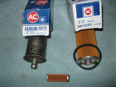
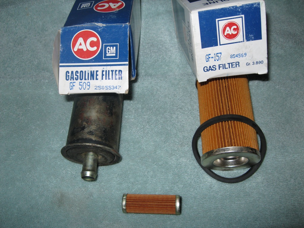
The small filter is in the carburetor body, It is easy to strip the threads in the aluminum casting (Do not over tighten). There is a small plastic seal between the filter nut and the casting to prevent fuel leaks. Should be changed with filter! it is hard to see unless you are looking for it.
The larger cylindrical metal filter is the in line fuel filter. AC part # 509.
The large cartridge filter (AC # 147) is in the fuel line, mounted near the inline electric fuel pump that keeps positive pressure on the input to the mechanical fuel pump mounted on the lower right corner of the block. Passenger side. This helps to prevent vapor lock when the engine is running hot.
Not all chassis have this pump if you have one. The Manufacture was (is) Carter. Wish I could remember the number.
Pictures of the fuel filters used on P-32 Chassis with a Quadarjet Carb. 1980’s ...
-
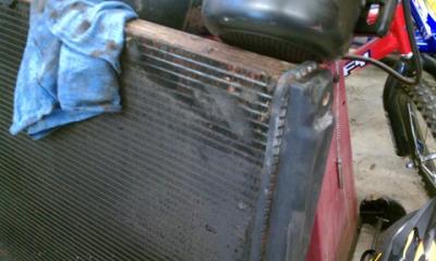
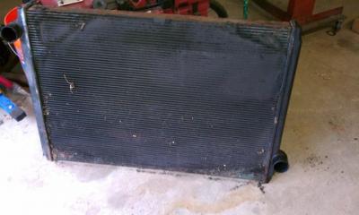
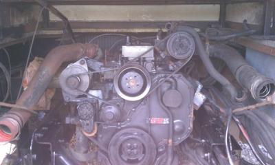
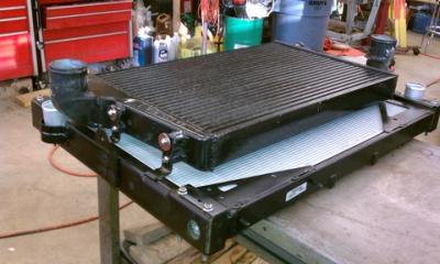
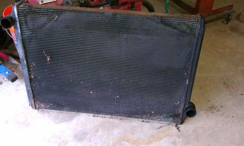
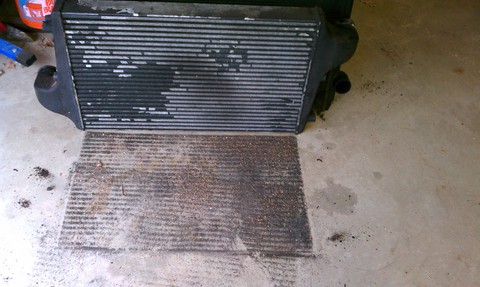
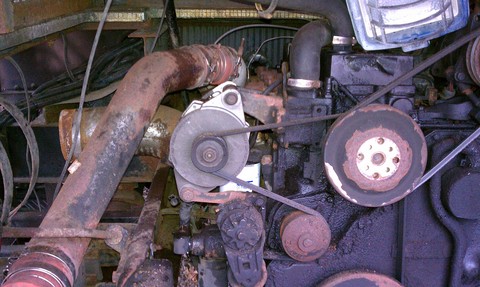
Here are pictures of the radiator, CAC and the stack assembly.
Pictures #1 and 2 -- radiator
Picture #3 -- CAC
Pictures 4 and 5 -- engine
Picture 6 -- stack
Freightliner recommendations
On chassis equipped with a rear radiator, it is very important that the radiator and charge air cooler be inspected at regular intervals. Cummins® recommends inspecting the charge air cooler every 7,500 miles. This is because air and dust blown through the radiator and charge air cooler can build up and reduce the airflow through the cooling system. This is considered part of normal maintenance.
From the engine side of the radiator, use a flashlight to look into the fan shroud at the face of the charge air cooler. If there is any dirt buildup, this should be cleaned using a water hose and a mild solvent. If this is not done, the system can become clogged and can result in engine overheating.
I hope these pictures will help others understand the importance of keeping the area clean. The side-mount systems do not get dirty as quickly, but they still need to be cleaned.


-
How many miles on the Engine? When where the fuel filters changed last? Does the check engine light stay on after you shut down the engine and turn on the ignition again?
You could have picked up some bad fuel,if it started after a fill up.
A number of issues could be causing the problem,need more information and then more able to address to your problem.
35 plus years driving Coaches, only a 2 year member of FMCA. Currently driving an AD unit.
-
A little more info. If you have 2003 or newer ISC Engine. The 237 Code for the engine with a HPCR Fuel system.
237 External Speed Command Input (Multiple Unit Synchronization - Data Erratic, Intermittent, or Incorrect
Not a thing pops up for the 313 Code.
****.
-
When you set up your Silver Leaf screen,did you set a Battery Level Window? I have had the Check Engine come on when the Alternator voltage goes higher then 14.4 volts and lower then 12.8 volts.
The other problem I still have is after the coach sits as little as 30 min. or sometimes it takes a few day the check engine light comes on, and as soon as I put it in gear and move like 10ft. it goes out. The ECM is looking for the Transmission pulse for the speedometer and cruise circuits.
Silver Leaf will log false codes at times due to noise in the 12 volt power, due to a bad ground (When the Alternator was replaced did all the connections get tightened properly) and any ground points for the 12 volt systems must be clean and tight. Loose connections at screw terminals can happen, just traveling down the road over time.
Did you try to read the trouble codes directly from the ECM using the fault code read back switches and the Check Engine Light?
Under the dash, locate the Check Engine Sw. and the Idle Increase Sw. Generally around the steering wheel column.
To Read engine codes on the Freightliner Chassis:
(The code must be active. i.e. Still showing as a Check Engine or other fault)
1. Shut the engine off.
2. Hold the Engine Check switch down. Located down by the steering column.
3. Turn the ignition key to on.
Both the Check Engine (yellow) and the Stop Engine (red) will come on
momentary. If no fault is active, both lights will come on and stay on.
4. The Fault Code will flash in the following sequence.
First, the Check Engine (Yellow) lamp will flash. Then the Stop Engine light will
flash the error number's in sequence. There will be a short one or two second
pause between each number. When the number has finished flashing, (in red), a
yellow light will appear again. The three digit code will repeat twice in the same
sequence.
The lights flash each fault code out two times before advancing to the next code.
To skip to the next fault code sooner, or back to the previous code, touch the
switch labeled Idle Increase/Decrease . This is a center off rocker switch located
next to the Engine Check switch. If only one fault is active, the same fault will
flash again.
Hope this helps.
-
The other Possibility is a loose connection in a junction box located some where. They should be pictured in your electrical drawings. The junction box might be exposed to the elements and the connections have corroded.
The fact that the lights are connected to a working circuit eliminates a loose screw at the fuse box. Things due loosen up driving down the road.
Hope these thoughts helps.
-
There are fuel filters in the Carberator ( 454 =s a large guadrajet) at the front of the carb. and an inline filter, generally located just forward of the rear axle.
If your coach is like my old 87, it may have two fuel filters in the very last pod area on the curb side. One pre auxiliary fuel in the fuel line to help prevent vapor lock and one post pump. This gave me a total of 4 fuel filters.
There maybe some foreign material in the fuel tank that has fouled the filter(s).
New in 2010 to FMCA. Driving a Class C, A and AD sense 1973. They just got bigger over the years !!!
**** ---F415802
-
Hi Altergrigo,**** Here. I owned a 1987 Gas Bounder and still have all the Chassis Wiring diagrams,my scanner is out of order at the time and I have not converted the files to a PDF format.
I currently have a 2000 Diesel Bounder and have been doing most of the work myself for years.
Might be able to help and you can join The Bounder.org Group at Yahoo and there are about 480 bounder owners at the sight.
****.
To late smart!! should have made a copy of the 87 Owners Manual.
-
A check of the Off Road Magazine sights might get you some good information. They have to balance the tires somehow, a neighbor had a mud truck with 48in. tires and he used golf balls to balance them.
I use the weight balancing powder in my 22.5's and it has worked well,takes special valve stems to keep the powder from fowling the valve seal. However ! I still have one stick open from time to time when airing up the tires,I just add some more air and just one more shot usually clears the valve. Just a little water on the valve stem is all ways a good way to check for slow leaks,no bubbles is always a good sign that things are air tight.
****.


Ice Maker in Dometic RM7030 Stops Making Ice
in Systems and Appliances
Posted · Report reply
Thinking that water is freezing in the water supply line where it enters the ice maker. When the water valve colses the water remaining in the supply line should drain down in to the tray area.
Have you tried to reduce the size of the ice cubes?
The problem could also be caused when the coach is tiped / lower on the side of the back of the refriderator,this could alow water ice to slowly build up and block the filler.
D.M.