


dickandlois
-
Content Count
4234 -
Joined
-
Last visited
-
Days Won
12
Posts posted by dickandlois
-
-
The bigger issue I'd also like to understand more is how the "cranking reset" button and the related circuit works. I can't find it on the manuals I have. Hoping someone has some experience with this.
Richard, Thinking that the generator might not have warmed up enough to be running at the proper speed before you added the 5000 Watt load. This could very easily caused a higher current level, because frequency and current are closely related in this case.
When you find the cooling issue, run the generator a little longer when it is real cold out before placing a large load on it - something like a 60 watt incandescent light should not cause enough load to trip the protection circuit in warm up cycle.
Rich.
-
Richard, Think checking the Thermostat is kind of at the top of the list. Cold weather can cause them to do strange things, also I'm sure you have checked the freeze point, knowing where you live. Is the water pump belt driven? Cold stiff belts can cause issues, how is the belt tension?
Back to the thermostat - I have had the top saddle that holds the spring in place split at the top and then they do not open properly! The valve assembly twists sideways.
Rich.
-
Phil, Thanks for posting the information. I'm always looking for little tidbits.
Rich.
-
marysteeves, The J 1939 is indication of a data network issue. Is the coach transmission operating Normally?
The other questions are what gauges do you have? Fuel level, Oil pressure, Water temperature and Battery voltage. What else ?
Do you travel with a GPS system? this should give you road speed. The gauges I mentioned are critical. One of the members on the forum is a certified Diesel Mechanic.
Thinking Joe will chime in. He is located in Southeastern Pa. Also a Diesel owner. Good source of information and real close to the RT. you will be taking. Also, Freightliner Factory Service main service center is located in Gaffney S.C. They have a parking lot for the Coaches with shore power, water and a dump station.
You might want to give them a call and see if they could squeeze you in, you will need the coach Vin number specifically the last 6.
Phone #1-855-253-0421, 103 Campus Drive
Rich.
-
3 hours ago, ElizabethMeyer said:Manholt,
Both the Cummins tech and the Allison tech have plugged in. Multiple times. Cummins shows 100% response to TPS full throttle request in "working" and "not working" modes. Allison shows 100% in "working mode but only a partial throttle request in "not working" mode. What the Allison computers shows in "not working" mode is what I term a rolling throttle response. Meaning, that when I have the pedal to the floor, instead of seeing 100%, Allison sees a request for 40% that then rolls up to 90% or even 100%. It doesn't always hit 100% often pegging around 94% throttle request.
Mark
Mark, My question regarding the percentages the Cummings ECM see's and the Allison TCM see's. Do they both receive the TPS (Throttle Position Sensor)information from the same circuit? or is the transmission receiving information from the Intake Manifold pressure sensor? The amount of fuel available and the intake manifold pressure readings are used by the ECM to determine the proper mixture over time.
The Turbo Boost increases over time as the RPM's increase and this will cause a delayed increase in the percentages displayed. Have they measured the turbo boost levels over time and the fuel lift pump pressure / and flow rate over time,relative to horsepower / torque?
Is the issue caused by changing or low fuel flow - even if the TPS is reading at 100% and
The 2 control modules are talking to each other over a CAN network. These networks are well know to have data dropout due to cabling and connection issues.
The ECM should be supplying engine status to the TCM - so is knows how much power is being requested to reach the proper gear.
These 2 piece's of information need to be all-way's exchanged - if the engine or transmission is sending the wrong information - it is still being exchanged and no Error Codes will appear or display IMHO.
The devil is always in the details.
Rich.
Just a personal note regarding the Cummings lift pump's. I have replaced a number of them for low fuel flow and low fuel pressure issues.
-
Mark, One more Question ?
Does the problem happen when you first start the engine ? or after things warm up any you have driven for a length of time?
Think I know from you OP but just want a conformation from you !
Rich.
-
Mark, Excellent explanation of the issue ! The primary Modules have bee replaced - if I'm reading your information correctly.
There are 2 items that could cause this issue that have come up over time, that I know of. One is the intake manifold pressure sensors and the other is poor ground point.
The ground(s) are supplied by direct connections or through relays during the start cycle. Should the Logic circuit not get a ground - some times a circuit will not toggle. No error codes would tend to make one wounder if the issue is in a throttle subsystem or intake manifold pressure sensor system.
Please post what they find on this one.
Rich
-
Pete, Did the fuel Consumption go down or did you mean to say it went Up?
Did the acceleration drop off, with a decree in power to climb?
Sounds like a leak in the boost system. That could be a number of items. Leak in the silicone coupling hoses or just a loose clamp, then it might be a blown gasket, at the exhaust manifold, turbo connection or gasket, cracked in the exhaust system. Then it might be an issue with the Turbo bearings - causing a speed change of the turbo spools / causing rapid changing Boost pressure.
How many miles on the coach and has the Turbo or exhaust system been serviced ? Not going into the CAC / inter-cooler at this time.
Rich.
-
Jerry, Welcome to the FMCA Forum !
I have a 7,500 Onan and change the oil and filter every 250 Hrs. You also need to change the Air filter and fuel filters on a regular schedule. First I would get a Cummins Member 10 % discount Card and have them do the job. Your Generator is a rather expensive piece of equipment and many RV service centers do not have the parts and need to order them and you will not get a discount.
You'r fuel usage must be a considerable expense. Thinking some cost annalist is in order - it might be less costly to stay at some campgrounds.
You might look at reducing the use of the AC to only the hottest part of the day, Or Park at higher elevations until it gets to a cooler time of year.
Rich.
-
Carla, I have a good friend in the area that owns a DP and has the work done in the area.
The problem is they are close to the wild fires at this time and have there hands full. Timing is everything. As things settle down - I will give the a call and ask John who he uses.
Rich.
-
Bill, I just finished looking back through the entire thread. I have to agree with you.
Battery Isolator's can do strange things. There are Diodes in them that can brake down when they get hot. Thing is it is unusual for them to work when they cool down, But I have had it happen on 2 alternators. To reduce the problem _-I in stalled some duct work to inject outside air directly into the area around them. This has extended the alternator life.
Good luck bburns and thanks for filling us in regarding you travels South away from the storm.
Rich.
-
Lithium battery charging.
Can I charge a lithium battery with a normal charger?
The “return to bulk” voltage setting in lead acid chargers is normally 12.5-12.7v. This voltage for a lithium battery is way too low. ... A lead-acid charger that can be set to charge no higher than 14.6v can be used for regular charging and then MUST be disconnected after the battery is fully charged. Lithium batteries do not like to be in a float charge.
I feel very comfortable saying that 99 % of Recreational Vehicles, cars or trucks charging systems, are not compatible with them.
My personal fear is there is a high probability of fire in the transportation and Recreational industry !
Take a look at this link. Covers a number of items related to batteries.
http://www.enerdrive.com.au/can-charge-lithium-battery-lead-acid-charger/
Lithium batteries are totally different and a true charger for large systems is not available for the consumer at a reasonable price. Also, they are good for short burst of current, but questionable for extended loads – like powering inverter’s.
Rich.
-
Thing to remember is - There are a number of chargers already install in RV's that are not setup or compatible to charge Lithium Batteries.
Replacing the Charger / Inverters can be pricey !
So look before you leap.
Rich.
-
Glenda, Welcome to the FMCA forum !
Most cigarette lighter circuits are fused at 20 amps, but it is always good to know for sure. Then Look and see the maximum current the brake controller and the GPS requires, before buying. One does not want to have a fuse blow while using the brake controller going down a long grade !
There are different stile splitter's on the web. look close to make sure there is enough room for it to plug in.
Rich.
-
1 hour ago, sherrycasteen said:Where to pull electric from on curbside for rear curbside outlet on Monaco 2002
Sherry, are you asking where to plug in 120 volt items? There is frequently a GFI outlet in one or more of the curbside bays.
Rich.
-
bobgdesige, Welcome to the FMCA Forum !
Thanks for the information. Can not say I have seen them at our locale Walmart. There is a family run store in the area that is a cross between an Army surplus and Radio Shack. Every tinker needs a location to find items to play with.
Rich.
-
Things are very confusing when it comes to transmissions used over a 4 year time line ( and that gets muddied even more depending on engine options - when you through in the 6 L, not used hear for one coach - but not sure about the other.
Could the original posters please inform the forum as to how many forward gears they have ?
We might be able to brake it down this way
GM - 4L185 has 4 speeds with over drive and most likely equipped with a Tow / Haul button.?
The Allison 1000 series has 5 speeds with 1 overdrive.
The Allison 2000 series has 6 speeds with 2 overdrives.
I have a number of the electrical and chassis drawings But the Chassis W series is different by year and over all length.
To Make things more confusing - there is no mention of what transmission was used.
As Brett might say, Not in my pay grade LOL
Rich.
-
Jim, Thanks for the feedback ! Could you post the The chassis you have? Thinking the part info might be Chassis specific.
Rich.
-
Graig, Great work! The brain was smoked last night, so I needed some down time.
It was wonderful to read that the issue has been solved! The information below was where I stopped. The marks on page 1 of the drawings went right through the problem area.
After that I went into the VIM and made up a chart of all the input and outputs to see if there was any possible items that could be connected to the sense relay coil power and you found the the common point! Really good work on your end. The failed part caused a oscillation in the loop of relays. That buzz in the one relay when the the engine was running or not was caused by loop when the that pressure switch failed.
Sent you the wiring interface info for the VIM in a PM that you can open and file with the wiring info.
The info below describes the wiring and circuit 125 F trailed off towards the VIM module (No electronics in it, just a number of relays and cross connect points)
The Camera and the jack power comes from the neutral sense relay. Body Builders connection. Lower lift corner of page 1. Those 2 items have low voltage / dimly lite. From Circuit C 409 / white wire neutral. sense relay! When Not Energized. From The Cab / Engine Harness - right side of page one.
It appears the sense relay coil power is getting an unwanted voltage from circuit 125-F. That also powers the park brake relay coil ! That voltage is being supplied from pin F-1 of the cab harness. Need To Change to page 2. circuit 125-F powers pin-B of the park break buzzer switch.
Please understand that the Chassis wiring is totally different on many coaches, but the issue(s) noted here most likely are caused by a shorted component. Diode, Relay, switch, wires or connections. The best person for the job most likely is a tech that works on system control circuits. They are a different bread and most likely work on assembly lines, production, traffic control systems, Elevators, Railroad control systems and last but not least are the techs that work for all of us. The military personal that keep all of the high tech equipment running.
Note! When the coach has a relay that is buzzing - there is a strong possibility the voltage will read low. When this happens the only way to check the supply voltage correctly is with an oscilloscope . The waveform will a square wave or a modified trapezoid. This indicates a shorted component, causing a feedback loop. All the relay coils that read low or share a common 12 volt source will read the same coil voltage. The component in this case was the park brake buzzer. All 3 contacts shorted together.
rich.
-
Craig, You mentioned Fuse Voltage - I think. Could you tack some voltage reading at the fuses, list each one that reads other then 12 volt? Then remove the fuse and see if the voltage is coming from the 12 volt bus supply or from the end of the fuse that is powering a system or control board.
The only item that has an issue is the chime relay when the engine is running it buzzes. I do understand that the brake light and cruse system appear to be dysfunctional.
Rich.
Got to take time to go get a hard copy of the wiring.
-
Kay, Think that is possible,but a digital meter can be an issue also. The leveling system and backup screen also indicate the low voltage. Need to find the common point for what should be a stady 12 volts. There has to be a common point feeding the systems - cruse control is connected directly to the ECM . That is a reach ,but is a possibility.
Rich.
-
Craig, I will look at the drawing area ! I did do some editing to my reply - so you might want to reread my thoughts. You do have a few hrs. head start on me ! LOL
Rich
-
Craig, Just open the file ! There are a number of Differences between your chassis wiring and mine.
A quick look and the cruse control and brake light circuits are - joined at the hip ! When you press the brake peddle - the cruse is disengaged and needs to be reset manually - when you press the coast / set button the cruse sets at the new speed setting plus the chime These 3 items you listed as having issues are in the same general area of the wiring harness have wires running outside and under the chassis also.
The Park brake relay has issues when engine is off or running - if I'm reading your info correctly. This fact kind of leads me away from the alternator and towards the dash wiring ! Because of the proximity of the problems. Going to look at the park brake circuit real closely - Oxidized connection or wire damage ?
Tracing the wiring is a slow / tedious project and can be labor intensive. Think I will copy the drawings onto a flesh drive and get a hard copy printed out! These drawings are generally in the 11 x 17 in. format. I then work to trace out the circuits and color code them with colored pencils.
Your issue kind of popped up overnight> By chance do you have squirrels or other varmints at your camp sight. The little devils love to chew on wires !
Rich.
Edited this post on 12/02/2018
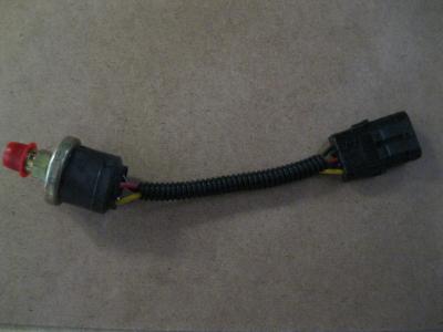
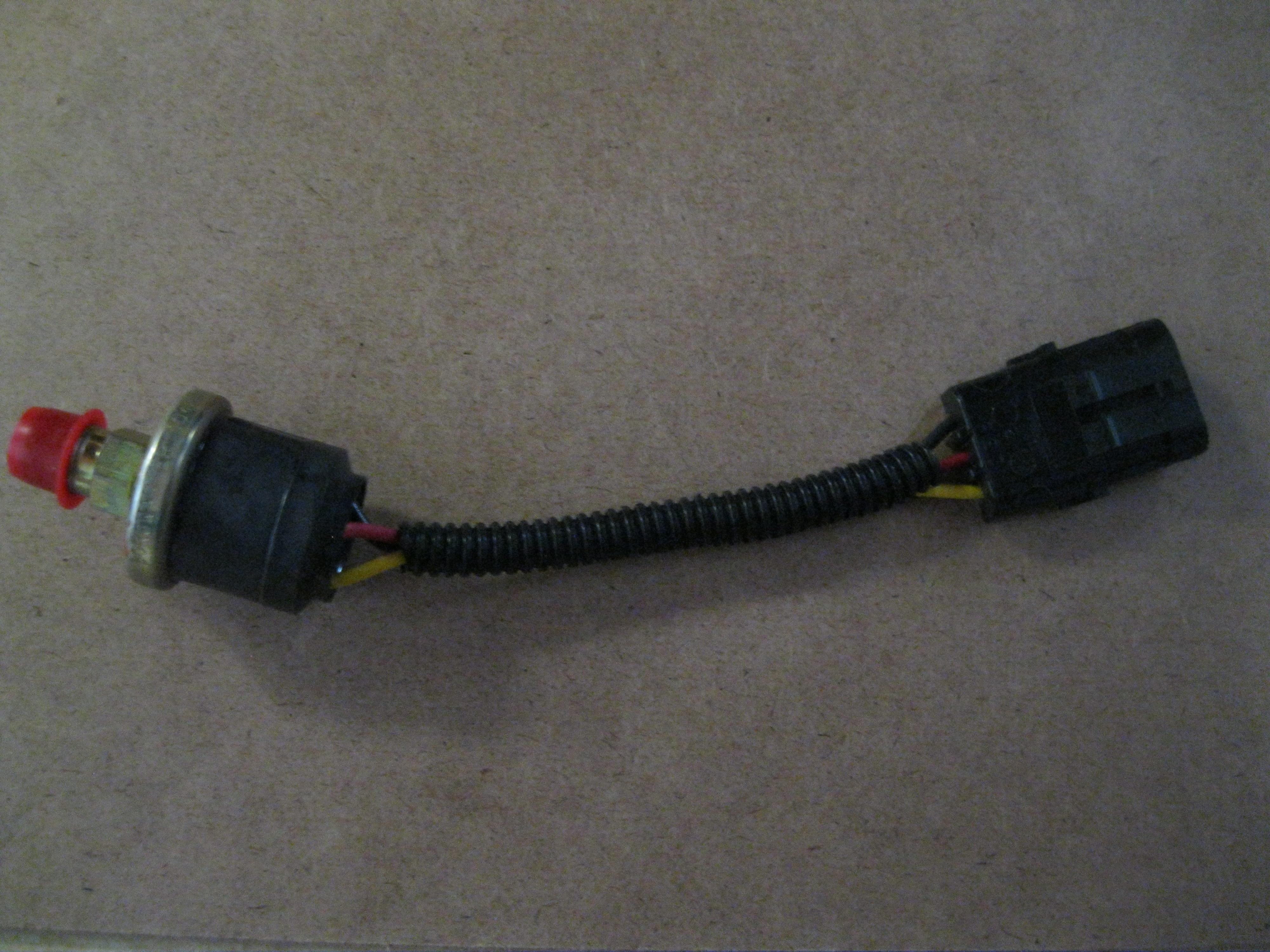
For Those interested in a picture of the offending part I attached a picture, this part was compromised due to water and dirt intrusion. Shorted the 3 internal together and caused the buzz in the relay circuit in question. The Buzz was caused by a Mechanical Oscillation caused by the shorts inside this Park Pressure Sensor. When the system was aired up or not! In this case the part was located - drivers side near the rear axle. Part cost around $100.00 The labor finding it can be a killer! NOT All systems use this type of setup, but do not over look it.,
-
Craig ! Could you pass on a copy(Attach a Copy) of the electrical PDF file that Fleetwood sent you?
Think you have the Allison touch pad setup - I have one of the last mechanical shift lever systems and my electrical wiring will not match your's
Does the chime normally come on when the ignition key is inserted? or is the chime you are talking about related to low air pressure?
Need to isolate the 12 volt source feed to the items in question !
Rayin mentioned a possible ground problem - loose connection, but most of the grounds in this case have 1 common ground point under the dash.
The parking brake relay in the electrical compartment above the generator is the one that’s buzzing, removing it gets rid of all the problems
The coach starts & seems to operate normally except the brake lights don’t work & the cruise doesn’t disengage when brakes are applied.
Installing or removing the parking brake relay with the engine running doesn’t change anything except the relay buzzes.
Rich
What Model Journey do you have?
Kohler 12.5 RCOP67 Generator Problem
in Electrical
Posted · Report reply
Richard, A question I do not have direct knowledge on, however! I have a thought running around in may head. Remember the calculator is not as quick anymore.
Does the generator start off it's own battery in your system?
If the battery is charged directly from a bridge 12 volt rectifier board or from a electronic speed control circuit(Different gen builders introduced things over different time lines. You Diesel engine setup was most likely built when I was in high school or a freshman in collage and I thought they where using smock and mirrors to totally mess me up. LOL
Your setup may very well have a mechanical governor - that removes most of any electronics and at a time when they where using the old diodes(Germanium) that smelled like rotten eggs when they failed where in vogue. This is where the gap in may information falls short - Nothing on the dynamo wiring and electrical interface.
I know you have skill levels many do not have, so if you can trace the wiring from the circuit breaker back to a origin - we might be able to open a few doors. Known info. it is a 12 volt circuit.
Rich.