


dickandlois
-
Content Count
4234 -
Joined
-
Last visited
-
Days Won
12
Posts posted by dickandlois
-
-
The Water pump relay is generally in the same bay as the pump often in the same bay as the fresh water tank. That is a good starting point, in your case you should be able to hear the pump running.The fallow wires from the pump and they should lead you to the latching relay. Try to read the information on the pump label - Wright down all the info you can find. once you trace the wires back to the relay - wright down all the information you find and post it on the forum.
A owners manual is shipped with every coach along with a file of other information from the factory. If you do not have the information, then you will need to contact Tiffin and ask how you get a copy of the manual and the paperwork file on all the equipment used to build the coach.
https://tiffinmotorhomes.com/owners/service-center
Rich.
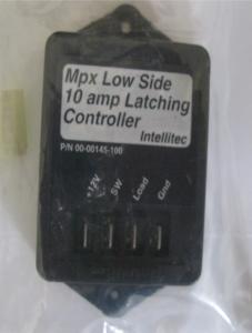
Common Water pump latching Relay
-
Charles, I'm closer to your home base then where you are at the time.. Some of the other members of the Forum will be more helpful with service locations, but This is some information on the Spartan Chassis. Recall information, The first page or 2 deal with the dump valve issue.
Rich.
-
On 8/22/2018 at 4:12 PM, redeye2 said:I HAVE A 2007 TIFFIN CLASS A OPEN ROAD rv AND WHEN I TURN THE WATER PUMP ON THE COACH LIGHTS FLICKER AND SOMTIMES THE dc SWITCH TURNS OFF, HAS ANYONE HAVE AN IDEA?, WILLIAM SHEFFIELD MEMBER F481199, THANKS
William, what is the model of your coach open road?
Allegro, Allegro Bay, Allegro Bus, Phaeton or Zephyr And the floor plan Number ?
Do you have the Owners Manual?
What water pump is installed ? Is it the OEM pump or has it been replaced ? What Latching relay is installed ? 7 amp, 10 amp or higher?
Is the ground connection at the relay and the pump clean and tight ?
Rich.
-
Lawtonr, Welcome to the FMCA Forum !
Your coach has 2 slides, Bedroom and Dinning area - Where did they mount the control panel? Are there any numbers on the control panel or letters?
This is the link to owners manuals. https://www.fleetwoodrv.com/rv-owners-manuals
Looked at it and there is a Terra LX listed ! that owners manual should cover the 32 K.
Rich.
-
Looking through some of my files and found this information that might be helpful to those trying to understand where Torque to Horsepower points are in relationship to RPM's and where these engine maximum performance point is.
Chevy 8.1
Just as with horsepower, the 8100 Vortec torque varied -- in small increments -- between 2002 and 2006. In 2002 and 2003, the 8.1-liter produced 455 foot-pounds of torque at 3,200 rpm. From 2004 through 2006, the engine's torque varied from 440 pound-feet at 4,200 rpm to 450 foot-pounds at 3,200 rpm.
The Max RPM is 5600, the power go’s flat at around 5200 RPM
The Engine torque varies from 2002 to 2012 depending on how the engine was setup to meet EPA standards in most cases.
Read More at http://www.ehow.com/list_7430500_specifications-8_1l-engine.html
Ford Trident V-10
Torque is 457ft.lbs. @ 3250RPM and 362 horsepower @ 4750 RPM
This means that above 3250 RPM the torque decreases as HP increases till 4750 RPM
Rich.
-
Richard, Good thought! Totally forgot about the front heater supply hoses, heater core and the supply valves. I had to fix the one on the return line, on our coach that was located on the drivers side, at the middle of the engine and about the same level that the oil pan bolts to the engine. The supply side valve is located at the back of the engine - engine head. They look just like an outside water faucet in our case.
Rich.
-
Has you oil level increased? A head gasket leak is also a possibility and might not be as easy to find.
Pressure testing already mentioned will find most cooling leaks. Water pump seal leak is difficult to see in Pusher coaches.
Rich.
-
The New owners of Coaches that plan to be traveling farther from their home base are not aware of some helpful items that will enhance usable information beyond what is offered at the instrument panels.
I understand that there is going to be a FMCA University available to members only in the near future, that hopefully will fill in some knowledge gaps.
So, stay tuned and keep an eye on the home page for information as the process evolves.
Rich.
-
Brett, your picture of a dirty radiator is much better then the one I have on file,
Damaged and dirty an not as well framed.
Rich.
-
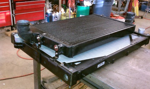
Mike, This is a picture of the CAC / Radiator stack configuration.
CAC / Air Cooler is the top / smaller "air to air" radiator and the larger / bottom portion is the coolant radiator.
Rich.
-
Mike, Brett covered things well. Regarding the synthetic oil. Back a month or so ago - I questioned the backwards compatibility of T-4 compared to the T-3 and the consensuses was (if I remember correctly) was that the full synthetic 0-15 or the 5-15 blend was not meant for engines prior to the 2017 engines that need the new blends to meet EPA regulations.
Regarding the use of the exhaust stacks - Coach builders often recommend them in there owners manuals. I have used one when ever we are parked in an area where one can run them 24 / 7. the exhaust will trip the Co detectors real fast if the exhaust is not vented upwards. Kind of thinking that Onan is covering a legal requirement, just in case the exhaust pipes have any leeks and there would be the possibility of a build up of Co.
Rich.
-
F438921- your coach used the information posted in this box. The Aladdin system was a proprietary system built just for Monaco and is NLA. So when it goes south you will need to come up with an alternate system. for your's'
page 330 of the manual indicates that it is an "Aladdin™ System" displays many AC and DC electrical values,
VSMpc is made by Silverleaf and can be interfaced into the existing Dash gauge system wiring.
However, silverleaf monitors the engine and I'm not sure it can be setup to monitor the Electrical monitoring system you get on your current display. You might need 2 different systems one for the dash display and one from a Charger / inverter supplier.
Good luck ! Rich.
-
F 438921- What is the model and make of your EMS or PCS system?
All I see in the original post picture is ESCo. Elkhart Supply Corp. and I can not find any info. on a Energy Management System supplied by them.
Just power transfer systems.
I see SONY lable under the system supply screen and that information is coming from a system monitoring module somewhere.
Rich.
-
39 minutes ago, kaypsmith said:Most likely, after studying the manual that Rich supplied, that makes sense.
That being the case - the batteries would not last for long running the AC unit. To supply around 14 amps of AC from the inverter would require around 140 amps from the batteries or a 10 to 1 ratio.
However, when you look at the frequency readings on the pictured - there is a one cycle difference on the FRQ readout between L-1 and L-2. One would question why there would be a difference in FRQ.
This is getting interesting to say the least!
Rich.
-
Kay, The L-1 circuit powers the Inverter / Charger in most of the systems I have run into, because that is where the 30 amp adapter is directed(unless the adapter is paralleling the L-1 and L-2 at the 50 amp socket end) That still would limit the maximum current to 30 amps. Unless the 30 amp is being supplied from the 50 amp breaker, that would mean the wiring is not to code.
2 and 2 are not adding up !
His monitor is reading over 40 amps with the front AC running. This is a Newmar electrical power panel configuration on page 7.
Rich.
-
F 438921- What is the model and make of your EMS or PCI system?
Rich.
-
F 438921, This is a link to get a copy of the Owners manual for your coach if you do not have one.
https://www.monacocoach.com/resources/media/manuals/2005_Dynasty.pdf
Section 8, Page 347 has a picture of the mail and sub power circuit breaker panels - what is on L-1 and L-2.
The Current reading on the L-2 side might be the Water heater mentioned by Richard, I'm Thinking Engine block heater ?
Need to keep checking into an electrical drawing.
Rich.
-
Thanks for the update ! Things working is always good. Readings, look like you where connected to 50 amp service ? Did you use the 30 to 50 amp adapter at any point while taking the pictures?
Well after going through and checking every wire connection for looseness, in the ATS and in the breaker boxes and then blowing out the ATS relay contacts I then went and plugged into a 50 amps service everything worked fine. I then plugged into a 30 amp service and everything was good but the rear a/c would turn on and off due to too much load on the 30 amp circuit which is normal but if I ran the front or rear a/c separately it worked just fine. I'm not sure what I did to fix the problem but I think blowing out the relay fixed it as there must have been something in the contacts, either that or it temporarily fixed itself and the problem will come back again. I watched the monitor to see how much leg 1 and leg 2 were drawing for amperage and I'm not sure how things are split up and what runs on what. I have taken some pictures to show you guys. I thought the front two a/c units ran on leg one and the rear on leg 2 but I"m not sure now. I will look and see if I can find a 120 volt power wiring diagram for your coach's power distribution.
Think the fact that both L-1 and L-2 have between 117 and 114 volts in all the pictures, that they where taken when you where connected to 50 amp riser?
The other item that stands out is The Leg 2 readings - Rear AC on and this leg reads 25.3 to 26.6 amps when the Rear AC units are on. With the Rear AC off Leg - 2 is still drawing 13.1 amps. The key now is to find what is drawing 13 plus amps with the rear AC's off - I have run into this reading at least one other time. NOW remembering what caused this reading.
Rich.
-
1 hour ago, wayne77590 said:PowerGear uses the rack and pinion also. The motors run off 12v provided by the controller. The controller keeps the motors in sync. Load sensing stops the motor.
Interested in hearing what you find out.
Wayne, Power gear is now part of Lippert. I posted some information on one of the Power systems used on a Class A coach that mechanically looks like what the OP has in his coach.
His Phaeton has what sounds like what is described and uses the same stile sensors and maybe the controller.
Rich.
The Crash in 08 sure messed up a lot of the paper trails.
-
44 minutes ago, bburns8 said:50 amp
Then you have a Sub Panel with a 30 amp circuit breaker in most cases that powers the inverter / charger. Could you check and see if the charger is operating by measuring the DC voltage at the coach battery's. This is to see if the charger portion of the 454 is working and if so the inverter should be operating - if not then that requires some further testing.
Rich.
See Ross has a GFI in the same model coach located in a bay !
-
43 minutes ago, Bsobania said:I have a viair 88p. I used it for the first time last week to air my truck tires up to capacity, from 55 to 75 or so. The air compressor was not sufficient, it took almost an hour to bump up four stock size Chevy 2500 tires. It was also hot enough to remove my thumb print.
Your at the max load for your current Compressor. Time to look into one of the pancake stile air compressors that can reach 110 lbs. or more.
Rich.
-
Is you coach shore power wired for 30 or 50 amp shore power?
Rich.
-
1 hour ago, bburns8 said:Tested the GFI and no power IN or OUT.
Your coach has an Inverter / Charger ! Xantrex 454 series - 20 / 20. Two circuit breakers are built into the output of the unit .
If you have the electrical wiring, the circuits affected would be # 2 and # 4 . dining area and entertainment equipment and or the Microwave power. this is a common configuration.
The Last post, would indicate that the problem is a tripped 30 amp / push to reset power input breaker to the inverter / charger !
The one GFI that might be tripped is often inside a storage area above an close to the inverter.
Rich.
-
30 minutes ago, bburns8 said:The GFI outlet has 2 black, 2 white and 2 ground copper wires. Which one is the power IN and OUT?
Black is the Hot side - Low is Neutral - green is ground.
No power to the from the main power panel breakers in a 50 amp, or a 30 amp sub panel or main power panel in a 30 amp coach. Then you have to look at the output circuit on the power Inverter.
If you could post the Make , Model and Year of your coach would help.
Rich.

Loose linkage in wipers
in Chassis
Posted · Report reply
Welcome to the FMCA Forum !
I understand the supplier for of the OEM windshield system was. https://www.amequipment.com/
This is a link to the English language file. https://www.amequipment.com/home
Hope they can help you find replacement parts ?
Good luck Rich.