


dickandlois
-
Content Count
4234 -
Joined
-
Last visited
-
Days Won
12
Posts posted by dickandlois
-
-
The Hyd. leak is back by the transmission.
Can you tell if the leak is from the jacks or from the trans mission?
Do you get any transmission error codes?
For some reason the auto dump valve is not closing to enable the air ride to inflate . Does your system have a manual air dump Switch?
Rich.
-
-
However most new diesels require routine ECM updates, some manufactures will turn on the engine light after a certain amount of time requiring a reflash. Due to many breakdowns at work we reflash all engines built after 2014 at each PM interval, when they get missed we get an abundance of breakdowns.
Joe, A Texan would say that ain't right. Wondering how many miles or Hrs. between each PM interval?
Reflash required on all engines sizes built after 2014?
Rich.
-
The Flaw I see in the Tri-Mark door lock is the lock is engaged when the entry lock is pushed down on the inside when closing the door and is way to easy to lock the door accidentally.
Once it is activated and with no key in hand or placed somewhere on the outside of the coach, you are locked out.
I have used a rubber band to hold the lock lever in the up position, but rubber bands do age and need to be replaced as needed.
Rich.
-
1 hour ago, hermanmullins said:I have begun placing tennis balls under the wiper arms. It takes the pressure off the blades and they stay flexible. The blade isn't sitting with the pressure on the causing them to set up with a bend in them. Works for me.
Herman
I do the same thing, but it does not stop the wiper blade edge section from tearing away from the main body.
Rich.
-
This subject is not directly mentioned in any of the thread titles, so I placed it here.
This is a link to a Consumer Report that covered in detail. Hope this helps.
https://www.consumerreports.org/cro/wiper-blades/buying-guide/index.htm
I personally have had no luck in finding a wiper blade that lasts like the ones made years ago. Traveled for business and pleasure and had blades that worked well for up to 3 years. The new style wiper design portion that contacts the glass starts to separate from the main rubber structure supported by the metal or rubber beam starts to tear loose in 3 to 6 months.
Rich.
Secondary Link
Check for wiper blade quality by manufacture at the above link.
https://10beasts.com/best-windshield-wipers/
Some good information, but lacks information regarding longer blades.
-
On 6/11/2019 at 1:50 PM, jpippin@onlineok.com said:How often do you have to replace the shocks? We have a 42' Country Coach Allure with tag axle
The Shocks on our coach where replaced at 110,000 plus miles when new air ride air bags where install. The original Bilstein shocks where still working with little to no real decrease in their ability to dampen the ride quality. The Coach was 17 years old at the time.
Rich.
-
Interesting Richard and Carl.
Thing is for me, it looks like a sails pitch, with very little information on the voltage range they are talking about and what electronics is required to supply different voltage and current levels depending on what items or item is being supplied DC Power/Wattage.
Think things are much more complicated then what they are willing to share and complications beyond each cell construction add a high dollar level and less system life of say 30 years to recover the investment cost.
Salesman do there job, but I always ask what they are not covering - Cost versus investment return time line. Byers be-where.
The other catch is the service centers will not pay in the area of 30.00 per hr'. for well skilled and educated Techs. This type of power management requires more then a seminar and a certificate.
Rich.
This coach is not on the market yet, but it sure points out that power is not really free and things are more technical then one would hope.
https://newatlas.com/tuscany-generator-free-motorhome-concept/59029/
-
John, Welcome to the FMCA Forum !
Finding service in unfamiliar areas is always difficult.
You might try this link to find a mobile service and then ask if they have a location where the work can be done if needed or proffered.
One should always check with those familiar with the area and the BBB for some relative background information.
Rich.
-
Think it takes less space to print out up and down or just arrows then to print out(Extend jacks to level coach and Retract jacks to lower coach).
Rich.
-
1 hour ago, desertdeals69 said:If you can adjust your current charging systems to work with lithiums it will cost you $6K for six 100 amp lithiums and that should run about twice as long on a charge and recharge in much less time.
How does one get the required 900 CCA from a 100 Amp Battery?
What is the life cycle in years? One can get 10 years from AGM series. So does a Lithium Series Last 25 to 30 years for the price?
Rich
-
Carl, I think the EPA needs to make ALL the information of a mandatory change over to Lithium based batteries available on line and publishing the information in all printed forms and print outlets. There are a number of citizens that do not own a smart phone or computer and millions do not even have internet access.
The cost of changing everything that requires batteries could very well shutdown a number of things because of cost.
Makes one wounder who go into who's pockets with bribes.
Rich.
-
ISB 6.7 Liter runs well, just challenged when running up a long grade and like Carl. How big / size are you looking at?
Rich.
-
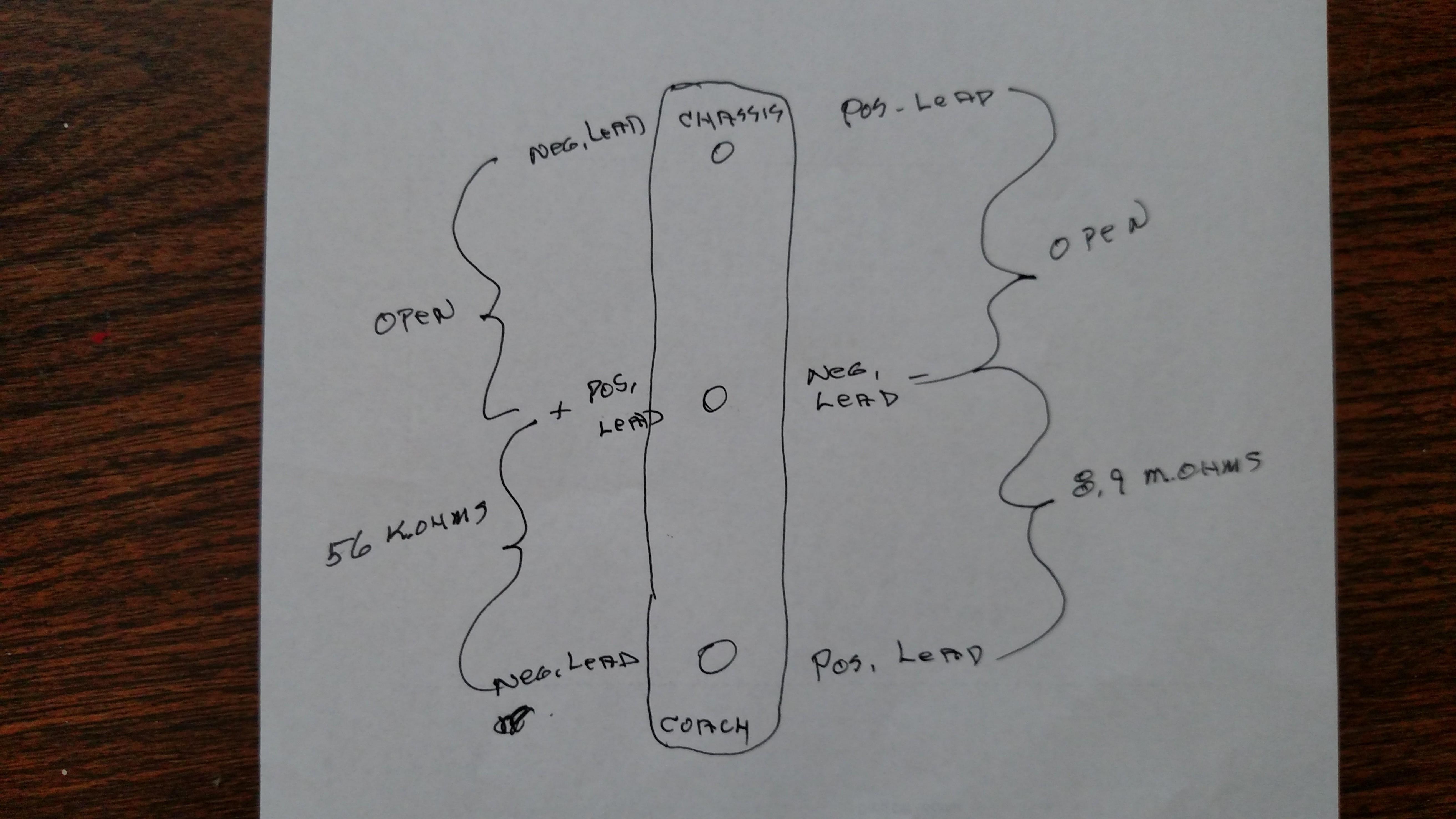
6 hours ago, floydfowler said:correction, should have been 0.3 ohms between the battery neg post and chassis ground.
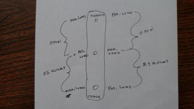
Floyd, From the reading you posted on the drawing it looks like the diode connected between the chassis and center lead has failed. That being the case, think you will need to replace the battery maintainer. Both sections between the center and the coach side and the chassis side should read the same or close to each other. Lost internet in a rain storm for a few hrs. LOL
This has happened when we get heavy rain over the last 5 months we have been parked. This time it was very inconvenient not being able to fallow the posts. Gr.
Just want to make sure the coach and chassis wires where disconnected during the test.
So Glad Kay was able to be a backup. 5 more appointments tomorrow. Hope the doctors will cut me loose so we can get back home to western N.Y.
I will be looking at the specs on the battery maintainer in the mean time.
Your willingness to keep hanging in there has been outstanding ! Reversing meter leads has happened to everyone using a meter at times. All you can do is laugh at yourself and keep on going.
Rich.
-
Floyd
Alternator:
Does the large alternator battery cable read positive 12 volts? when the engine is NOT Running ? The one that is missing in the drawing at the large terminal?
I have never run into a positive grounded Alternator on a US built coach or car.
With ign. off, I read -12V ., with ign. on, read - 12V
Ignition Terminal: ???With ign. off, I read -0.311 V and with ign on, I read -12 V between ign terminal and negative alternator terminal and 12.2 volts between ing terminal and chassis ground.
DUVAC Terminal:???I read 0 v with ign off and -.15 v with ign on. from duvac terminal to negative alternator terminal but I also read 12.8v between duvac and chassis ground.???
t is obvious the the negative alternator terminal is not grounded to the chassis. The alternator should be grounded to the Chassis, when it is bolted to the engine bracket.
SO ! Using your OHM meter read the resistance between the alternator. IT should read zero !!! or very low reistance -reversing the black and red meter leads and the resistance should read zero .
IF it does not then we need to see what is going on.
The Diode readings do not look right !!!!!
From ground terminal(center terminal) to both outer terminals using the red lead (the meter should read high resistance - 100 k to meg ohms. Reversing the red and black locations and the meter should read somewhere between 500 to 1,500 ohms.
The way the battery maintainer is wired from my view point would never charge the batteries. And if you read 14 volts or more at the coach and chassis batteries . The battery maintainer would slowly discharge them.
Rich.
NOTE. I did read your feedback about the resistance, want you to retest using the instruction offered. One of the circuits reads open both ways if I,m reading things right. I'm getting a bad feeling and I want to be wrong about the wire ring.
-
Yes get a reading of the current on the 2 outside wires .
Rich.
-
Do you have a current meter with a current loop clamp?
What is the reading?
Regarding the green box with the 3 wire removed( mark them so they can be replaced the same way they came off.)
Using the Ohm setting measure the resistance between the center connection being negative and positive to the 2 outer connections. wright down the readings for each one.
Then place the positive to the center and read the resistance for both of them. wright down the readings for each one.
Post the readings relative to the center being negative and the readings with the center being positive.
Rich.
From the information you posted the Charger is working fine when on shore power>
-
Floyd, Got to keep looking, interesting thing is the Alternator is pictured; but no cable connected to the battery charging post.
I might have missed the coach battery and chassis batteries wiring, but just getting started looking at what is offered in the drawings forwarded.
Rich.
-
Floyd, I understand, but the wire gauge indicts other wise . That is why I asked for the other part of the wiring.
For the coach batteries to charge at 38 amps. There needs to be a different path between the alternator and the batteries.
Will be studying the new information for now to see what things are wired like.
Rich..
-
Carl, The fact that 2 locations have the same issue, you might do a resistance test on the shore power cable. Good look at the riser end and and the power real end.
Joe beat me time wise LOL
Rich.
-
Good feedback Roland, think they are hot on the trail of the problem. The drawings do not always include the wiring covering the VDC.
If you are willing to forward the drawings, please do so and I will add them to the folder of Freightliner wiring info.
Rich.
-
Floyd, No problem regarding the use of a post that is somewhat relevant to the OP. So many different OEM setups.
From the wiring diagram portion you attached, it looks and the inscription mentions battery maintainer. That holds water because wire gauge is to small to carry a high current load one would see in the charging circuits. So the larger wire (#2 or 4 gauge ) would go directly to the chassis battery from the alternator.
Could you attach a picture covering more of the drawing on the right ?
Does your coach drawings show the invertor / charger wiring ? The coach batteries are not getting a high current charge from the alternator only about 5 to 10 amps from the green colored module in the picture.
Rich.
-
The Green box in the picture is the isolator ! They do fail. It is a diode circuit and it is a lot smaller then most I have seen.
Your system is using an isolator relay and It could be caring most of the charging current.
A diagram would be easier to fallow then the pictures. Do you have one?
Hope what I have offered helps.
Rich.
-
Traveler44, Yes Welcome to the Forum!
Could you post the part number, of the original controller(should be a number on the controller) Most of your year coach used Power gear hydraulic leveling systems.
You did post that the pump runs but no jack movement. Wiring difference or open ground to the valve manifold.
Rich.
Air Ride
in Chassis
Posted · Report reply
Think there is a possibility that the hydraulic leak in the system is the issue. The hydraulic system reservoirs generally have a level sensor and your auto air up might be in a default mode.
Suggest that you get the leak repaired and the reservoir filled to the proper level.
Keep us in the loop.
Rich.