


dickandlois
-
Content Count
4234 -
Joined
-
Last visited
-
Days Won
12
Posts posted by dickandlois
-
-
Rand , Welcome to the FMCA Forum !
HEUI pump is used on Diesel Engines, Best described as HEUI Fuel System. The Hydraulically actuated Electronically controlled Unit Injectors (HEUI) use a hydraulic pump and engine oil to generate fuel injection pressure, and an ECM to control the pressure and amount of fuel injected into the cylinders.
We tend to be creatures that like to add confusion to everything ! Like ATM - Automatic Teller Machine or Asynchronous Transmission Mode. LOL
Rich.
-
11 minutes ago, desertdeals69 said:That should work. I would also have a ground wire same size as the positive using your trolling motor plug. Have your fuses on the positive wire as close to the termination point at both ends.
This is a new term to me. could you enlighten me. Trolling motor plug? Thanks.
Rich.
-
Boosenbev. Yep< the panel reading is a mirror image. We did that with some security cameras years ago. Not what you want in this case. Somehow the display driver logic got reversed.
You have some good thoughts on things to try. Should the system not reset - I kind of think a call to the manufacturer and ask questions and IC in the circuit could have lost a logic input or it has failed internally - cold solder connection or the loose of a ground point.
Just when one thinks they have seen about everything a now one pops up. Just check if you can get to the back of the display and see if one of the flat ribbon cable connectors has Jared loose and one or more of the data connections is not making a good connection. The cables just slide into the connector and if when it was assembled / the assembler did not get the locking tab pressed in tightly.
Pictures are worth a 1000 words, the picture could make for some interesting conversation later on.
Rich.
-
2 hours ago, klparker said:2001 Itasca, two slides. The large slide will not always retract, and once the bedroom would not. I usually have to use the retract button several times to get it to retract. I can hear it trying to retract but I don't hold it a long time. When you store your motorhome for a period of time, should slides be extended or retracted?
KL Parker
KL, Could you offer some information on the model number and if is a Hydraulic or electric controller, also- whose system, HWH, Power Gear, LCI or other?
Rich.
-
32 minutes ago, Monacoman06 said:I have a 2006 Monaco Dynasty that uses 2005-2007 Ford F250-F550 truck headlights. I am wondering if anyone has switched over to the LED headlight bulbs and if so do you know which bulbs have to be changed? Are there both high and low beam bulbs or just one? Any recommendations for which brand or type bulbs to use? There seems to be many brands or types on the market. Thanks to all for their help,
The Headlights can be refitted with LED's if there is and aftermarket unit available that will match the OEM setup.
This is a link to members of FMCA with information on LED lighting and other items of interest.
http://www.thervgeeks.com/led-conversion/rv-headlights/
This is one extensive sight that might have a LED option.
Rich.
-
boosenbev, Yes, welcome to the FMCA forum!
Like Carl asked, Did this just happen and Could you post a picture of the monitor panel?
Rich.
-
Glenner, This is the best information I could find regarding the picture of the wiring you posted.
The diagram in the word format is the most complete. Need Microsoft word to open it. This diagram matches the board layout the closest and the relay / solenoids mounted on the board.
The second one I converted to a PDF file, did clip the wiring just a bit on the right side of the drawing.
The second PDF file is the complete chassis wiring for the 2005, P-32 chassis or L-18 that Workhorse used.
Glad the chassis fuse box information matches.
Good luck with your project.
Rich.
Note, The little black items connected in Parallel at the one terminal are counter EMP Diodes that protect the coils and the power fuses from getting damaged when they are DE- energized - They look like the right size to be rated a 6 amps and a PIV of around 1,000 volts. If you ever remove them try to get clear picture(s) before removing them. Proper polarity when replacing them is critical - so things work !! Energize properly.
-
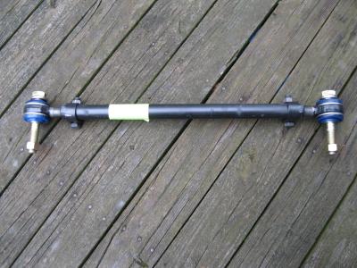
The other item that fails is the grease retainer that surrounds the mounting bushing.
The proper level and ride height must be attained before removing the track bar.
Rich.
-
5 minutes ago, wayne77590 said:Okay, just call me dummy. What is the purpose of the track bar? (Duh!)
They are used to center the chassis over the front Axle. There is a reference point used at both ends of the axle and when they are equal, the axle is centered on the frame. Who uses what method depends on the setup.
Rich.
-
Items like this that make me just want to shout ! The builders cut corners to keep the price down so they can compete with the market, but if things keep coming apart, How long before they are history.
Thing to keep in mind is Buyer beware and quite often one gets what they pay for. Then again in today's market when the company departments know there are issues - the top brass just will not except any negative feedback. Appearance and appeal will sell anything.
Rich.
-
HI G. This is a picture of a new track bar from Freightliner. Most likely it is slightly different then the OEM one ?
This link might help find what you are looking for. The page size can be enlarged - left side + an - Box. so one can read the information.
Think You will need some specific information to see if they can match up what you need.
Dayton Parts, LLC
345-714 to 354-7136
Numeric Listing
https://cld.bz/bookdata/uCKGlPu/basic-html/page-1113.html
https://cld.bz/bookdata/uCKGlPu/basic-html/page-1113.html#
This is an Ebay link for one, But structural dimensions are critical for the part and the total length adjustment affect handling and alignment.
Rich.
NOTE. This item needs to be installed properly to maintain proper alignment !!!
-
Noriser, Welcome to the FMCA Forum !
The tap needed to clean the treads is a 1/2 - 14 Tapered pipe Tap - The Mating Die is 1/2 in. NPT die.
This is not a standard stock item for many location like Lowe's or Home depot. Alfa tools is one supplier
Rich.
-
9 hours ago, jleamont said:Rich, sounds good! What pump did you use?
Joe, This is not a vendors forum ! LOL - So I can not offer any information or my personal views of the device. Is that politically correct?
It is a Fass DRP series that did not include the installation Kit.
Fuel lift capability is 4 ft. and a flow rate of 90 GPH. at 15 to 18 psi. The low number does drop as the engine load increases, but still is well above the OEM pressure levels.
Had to lower the pump about 2 1/2 in. so it would clear the frame rail. The pump mounts horizontal so the weep hole is pointed down, if not orientated correctly, the warranty is voided.
Used 5/16 -18 stainless steel rod to make mounting studs / jamb nuts at the pump mounting bracket an the pump mounting plate, long enough to drop the pump and clear the frame rail. I placed 3/8 in. threaded couplings over the rod(just a nice fit)to increase the three point bearing weight area of the pump adapter and the OEM mounting plate . The pump hangs out about 3 plus inches from the brackets and I wanted to limit the torquing affect on the mount.
The only item left to replace is the fuel input connection from a straight fitting to one with a 15 degree offset so the fuel supply line does not rub on the top corner of the Allison transmission.
Rich.
-
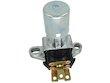
arthur.jeck, The P-30 does not use a relay - it has a floor mounted dimmer switch and is located on the floor left of the steering column.
This is a link to what the switch looks like and the same switch was used from 1975 to 1990.
The OEM connector / socket # 8900855. The center terminal is the common wire color Green, The high beam side wire is Yellow and the low beam side wire is Tan.
Rich.
-
"Now, if I can only find the leak in PS slide out."
Carl, does it leak only when extended or when it is retracted?
Rich.
-
8 hours ago, arthur.jeck said:It is a Class A RV on a P30 chassis
1988, P-30 Chassis think I have the OEM shop manuals for that one. Will do some digging into the old library. That info. is not loaded on the computer.
That makes things a little different then a Ford Chassis. The information I have on you model anf make mentioned the Ford chassis was used, but coach builders did use both in the time frame.
Rich.
-
On 7/30/2017 at 2:00 PM, DickandLois said:Been going through fuel lift pumps like candy from my point of view.
Going to start a replacement process of the fuel line, lift pump and filters starting tomorrow now that I have procured all the needed parts. Going to replace the 1/4 in. line from the last fuel filter going to the injector pump.- increasing the size to 5/6 in. line and install high flow banjo bolts, that restrict fuel flow from the first fuel filter output all the way to the injector pump input.
Will be taking fuel pressure reading after each part is replaced and get some flow rate readings, if my friendly mechanic will let me borrow the flow meter fro a few hrs.
I did call Cummins and did not get any real base line information on how long or how many miles there pumps should last. Thinking they have some test stand information and should be running spot checks on the new units being supplied.
However, going through 5 of them in 120,000 miles does not make sense as they drop below the specified 10 PSI minimum specification in the engine repair manual . When my big 8.1 L gas powered truck will go 125,000 miles on each pump. I'm not much for making the parts department richer.
Rich.
OK, I just quoted my own post to expand on the lift pump conundrum ! Edited 6-25-2018
I went and purchased an aftermarket lift pump and the difference is very obvious !
After finding a way to mount the pump in the OEM location , Connecting up the fuel lines and replacing the second filter. Because it is much easier with a number of things out of the way.
Connected everything up except the 12 volt power, made a jumper cable connection (making sure the polarity was correct)hocked the pump to one of my spare batteries and listened to the sound of the motor for maybe 2 to 3 minutes and then it started to labor. Went to the drivers set and bumped the starter - that worked -so I then cracked the engine for 20 to 30 seconds - no fire - bumped it twice more and the engine tried to com to life.
Then I looked at all the connections and checked for any leaks on the pressure side, NO leaks is good. Removed the jumper and the power from the pump, connected the pump to its mating connector.
Thinking that if I had a small air leak in the 25 to 30 ft. of fuel line running from the tank back to the pump, I would need to run the pump a few times to re prime the system. The engine sputtered for maybe 5 seconds and smoothed right out, let it run for a good 15 to 20 mins. no issues.
Then I oped the fuel line between the second filter and the fuel line running to the injector pump. THAT move allowed to system to loose its prime, but with the pressure gauge now in place I could see the pressure reading slowly rise to 14 psi before the engine started. Ran the engine at idle apx. 750 RPM for around 5 more min. Then got my DW to watch the pressure reading as the RPM's where increased to 1900. Fuel pressure dropped from 14 to 12 psi.
The thing that stands out is - the OEM pumps delivered a maximum pressure of 12 psi. that dropped to 9 to 10 psi when idling and dropped to 7 to 8 psi. at 1900 RPM.
Let the coach set over night and bumped the starter - The delivery pressure before starting the engine hit 18.5 lbs. Never have had numbers like that, but remember the VP-44 injector pump maximum input pressure is 20 psi if you do not want to kill them. Real good numbers again Started the engine and the idle pressure set at 15 psi. - increased the RPM to 1900 and the pressure leveled at 14 psi. this was a no load test. So I turned on the Dash AC and the load only dropped the pressure 1/2 LB. Will run to the Fuel pumps and top off the tank.
OK, Topped off the fuel tank and the fuel pump pressure increased by 1 Lb. Nice, fuel level in the tank increased by 12 plus inches, The pressure only increased a little. That indicates to me that this is indeed a much better pump in regards to its vertical lift ability !!
Then to get a road test in before being interrupted for like 2 weeks. Forth of July weekend - Road trip will need to weight for a few days.
after that I will see how this miner but impressive change affects the performance on a real road test, of 75 miles and a 3/4 mile climb at 9%. That one hits coming out of a 40 MPH zone.
Rich.
-
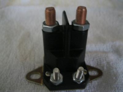
Herman, Question! Think that Gpippins is talking about the starter relay that energizes only in the start mode, not the ACC relay that is continually energized.
The relay used on the freightliner chassis is most often mounted where DD mentioned and the small wires come from the ignition switch and the relay contacts with the big wires runs to the starter solenoid.
Castle Relay ignition circuit picture - connected between the starter solenoid and the ignition switch.
Rich.
-
Michael, Welcome to the FMCA Forum!
Well from your list, you sure need to have the shortest coach on the longest chassis so you do not get hung up in a culvert. A short Class A would offer the most storage space and interior room per foot. They also tend to have a little more road clearance. Need to keep the bumpers as close to the wheels as possible. Might want to include a winch setup and a strong rear hitch.
The Four season item requires the ability to keep the water, gray and black tanks from freezing, this is the most challenging item on most small units. We have carried water in containers that can be stored inside and some antifreeze to add to the gray and black tanks to keep them from freezing as well as the drain traps. The Class A units also tend to have larger LP and gas tanks, with Gas Generators. That saves the LP for heat and cooking.
There are some units that are built more for wilderness camping, but you will need to prioritize some . Not everything fits in one box. Might want to include some solar panels ether mounted or portable to have a secondary 12 volt backup system to help charge the batteries.
Traveled around the West and camped on BLM sights plus Alaska - But not in the coldest part of Winter.
Rich.
-
Kay, Nice dark blue, looks like you found a nice bra for the front. I do need to ask if the front right fog light is setup for coon hunting while you are out cursing around the mountains ? Or setup for rock hopping at night around the Blue-ridge area?
Hope it works out well for you !
Rich.
-
Thanks for taking the time to inform all of the issue repair and where the leak was hiding.
Rich.
-
48 minutes ago, manholt said:Rich, why a 2006? OP has a 2011 Allegro Bus! Mine had 2 chassis batteries and 6 house! All electric coach!

Think I had another DUH Moment ? ,but I copied and pasted that model from a thread reply and there information.. Sometimes the brain is not on the same page or I have to many windows open at the same time.
Now to see if there is something closer to the OP year. Edits to follow.
Rich.
Carl, the battery connections in the picture attached by the OP do not look like the setup in the owners manual for the 2011 Allegro Bus?
Wounder if a previous owner added some extra circuits and no notes where passed on ?
Some of the clutter is from the terminal caps being removed from the connection posts, looks like the batteries are not on a slide tray and with all the filters above the batteries - impossible to get a good look at things
The information was copied and pasted from alflorida's post, my bad!
-
On 6/21/2018 at 4:57 PM, whale1999 said:Copied and pasted the wrong info.
Rich.
-
Glennr, The Chassis builder installed the fuse box for the chassis 12 volt and install 1 to 2 circuits for convince outlets, like the power steps and 12 volt outlets for cellphone and GPS power.
Work horse took over the P-series chassis, so matching things up can be challenging. I have 3 or four of the OEM - P series manuals. If you have a camera and take a picture or 2, I might be able to match some thing from that if needed.
Rich.


Can a 2006 Monaco Headlight be changed to LED
in Type A motorhomes
Posted · Report reply
Joe, see there is a cross reference - Do these bulbs or some of them require a conversion kit?
Rich.