dickandlois
-
Content Count
4234 -
Joined
-
Last visited
-
Days Won
12
Everything posted by dickandlois
-
Andy, Glad you clarified the girlfriend item, especially with Esq. after the DW's name. LOL Rich.
-
With the limit to the number of pictures one can attach to these threads. I have added some pictures and notes to my alternator problems photo gallery. Hope this helps others with similar issues. Rich.
-
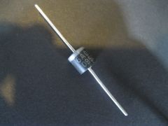
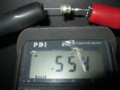
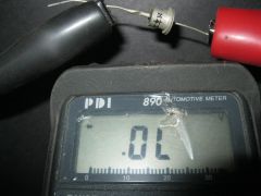
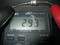
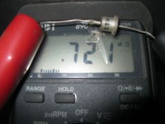
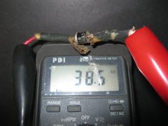
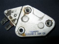
Pictures of a Delco Voltage Regulator and the inline exciter circuit diode.
-
-

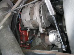
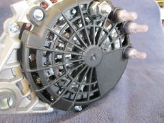
View of the back of the SI 21 Series Alternator
dickandlois posted a gallery image in Members Gallery
From the album: Alternator problems
This picture shows the terminal connection layout of this style alternator. I had to make only miner changes to the coach wiring in the Engine area to make the Replacement SI 28 Series alternator operational. Both Alternators are built in the J-180 Stile mounting frame. Note ! There are two different sizes to this style mounting. -
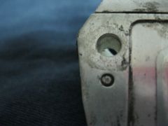
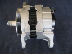
Side profile picture of the OEM SI 21 Seriers Alternator
dickandlois posted a gallery image in Members Gallery
From the album: Alternator problems
This alternator is rated at 13.5 volts, 160 to 190 Amp output current configuration for my application. The unit has a single external fan configuration. Although it is well within the required power requirements, in this case around 2300 Watts. It has repeatedly failed after about 18 to 24 months, due to a thermal breakdown of the regulator diode assembly. -
From the album: Alternator problems
The picture shows the connection terminals on the back of the Alternator. There is a difference in the exciter terminal connection and one of the 12 volt connections. 28SI SPECIFICATIONS Performance Output 12 Volts @ 200 Amps (140 Amps at engine idle) Maximum Speed 10,000 RPM Continuous, 12,000 RPM Intermittent Rotation--Clockwise Temperature Limits--- Low -40°C (-40°F) High 125°C (257°F) Polarity Negative Ground -
From the album: Alternator problems
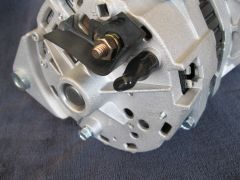
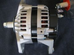
This is a 200 Amp, 14.5 Volt alternator that I installed in place of the OEM SI-21 Series Alternator that was on the Coach. This unit has 2 internal fans that I hope will keep the internal temperature within a range that the regulator likes, to prevent the thermal failures that have plagued me over the years using the SI 21 series alternators. The total current output and power output are also higher. The total power output of this unit is approximately 3000 Watts. The change out required wiring changes to the exciter / key circuit at the alternator itself and one 12 volt wire from the battery positive circuit. The OEM unit was replaced twice and rebuilt twice using different regulators. I was trying to fine parts that would withstand the heat in the engine compartment on my Diesel Pusher. -
Andy, as long as there s no play / wiggle in the ball joint all should be well. When its time to replace one, you will know when you do your walk around so to speak under the coach and one of them moves. You get the, that is not right feeling real quick. The fact that it was covered in grease,that would keep the dirt and water out of the pivot area. The seals are there to keep the grease confined around the area. Rich. P.S. A man after may own heart. Nothing like knowing your machine is ready to go. The little things can eat you up !!
-
Travlin, The answer is yes. You need a service shop, say HAVC center and one with the proper materials to make an access point in the cooling loop and the rest is about the same as any home AC system. Having said that one needs to know what the problem is with the unit. Is it just a starting cap., power circuit issue, circuit breaker / relay, cooling fan, (worst being the compressor) or a thermostat problem. Should the compressor fail, just replace the unit. Rich.
-
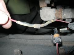
With intermittent problems one needs to check the ground connections. Very often there is a common grounding point. Regarding the fuel gauge, check for a bad ground connection or even a broken ground wire running between the fuel tank and ground. The senders need a ground connection, often they will read full or empty when the ground is missing. Herman point about the key switch is veiled. Also check the connection and connector behind the switch. Some circuits do run hot and I have seen times when the plastic connector holding the wires to the switch have melted. Rich.
-
1999 Safari Sahara, Magnum Chassis, Cat 3126b. Engine Won't Start.
dickandlois replied to bobgudde's topic in Electrical
Bob, I'm not an owner of your model. However, what you describe sounds like a blown ignition fuse. They are most often located in the fuse panel under the dash or around the front firewall. The coach should have a Battery Control Center that cross connects the Chassis and Coach battery circuits. There is an ignition circuit feed that goes to the center and often controls the start relays. It could be a blown fuse in the center. BCC's are connected and powered from the Chassis batteries,so its possible that there is a bad fuse in the ignition circuit in this unit. Do items like the power seats and foglights or any items not work in the coach that did before you changed the battery? Rich. -
I did not pull the dash per say. I removed the driver side set. This gave me more room to work under the dash,because I could lay on my back and get a better look behind the panel and the wiring. This allowed me to see what needed to be loosen to get items out where I could make sure the connections and cabling where in order. It is a tight spot. See if you can trace the power wire back to a bad fuse. I never did have any wiring diagrams,just made very detailed notes. I wish I could tell you that I had them so I could refer to them,but not the case. My wife informs me that I'm a pack rat. Mine did have a multiple pin connector from the harness going to the monitored areas to a connection that was part of the panel mounted in the dash area. With all the gauges not working, look first for a loose ground or power interruption.a single gauge would mean just that circuit had a circuit or connection issue. Hope this helps. Rich
-
There is a multiple pin Connector for the gauges that Read the Black,Gray,Fresh water,LP and battery levels that is temperamental. Check that one, its right behind the display panel. That is the only system you mentioned that is not working, so I'm thinking its just happenstance that it quit when the batteries where replaced. I did own a 87 Bounder and they did quite working twice and the connection was loose. Rich.
-
John, This is a link to a IRV2 sight and it mentions Diagrams for a 2001 Monaco. They might be close to your system. The poster was willing to pass on the PDF file. It might be worth a look, Rich. http://www.irv2.com/forums/members/alan+roberts-30447.html
-
The Questions are many! However ! The real big one for us would be coverage area of the plan / Network area. Canada / Mexico and where ever one might want to Rent an RV to travel with. Then it gets to cost structure and riders. Rich and Lois. This is an interesting thought. Not quite to full timing,but sure can smell the roses.
-
Lynn, Could you post the model of your coach. There should be a panel somewhere that lets one set the Heat and AC temperature. The fact that it takes over an hr. for the furnace to come on is not normal,unless the temperature is set close to what the temperature is inside the coach. Rich.
-
Alan, I have been looking around regarding your problem. You did not list the year of the coach, But I wonder if this recall covers your problem. http://www.automd.co...ampaign_c81614/ Rich.
-
Trip Routing And Campground Advice For Trip West/Canada
dickandlois replied to bobnshirlene's question in Destinations/Attractions
My thoughts are to contact the State and Provence tourist offices, they can be found on-line. There is a lot to see and way more then one can cover in the time you plan to be on the road. Look over the information you get back and prioritize. There are routes that will make the Coaches huff and puff and sections where one will be squeezing to seat and armrest. There are roads in the Glacier Park that the Coaches will not be allowed! WE have traveled that area for many miles over the years and somewhere around 8 trips spanning 3 weeks to 3 months. Good luck and Safe travels. Rich. -
Potential FMCA Member -- I Don't Have A Coach Yet!
dickandlois replied to jspila's topic in All About You
Interesting, You know that it might be a good issue to be brought up on the floor in August. One would think with just a little planing we could call prospective owners. Friends of FMCA. Thanks for shining some light on the question. Rich. -
Hi Ronnie, I will attach 3 Freightliner Oasis service center locations. They have 24/7 repair operations. The thing you might want to check on is if they have RV hookup and parking so you can use your Coach until repairs are made. They are all listed as Oasis centers but not all are equal. Some you could almost eat off the floor,an others not so. FREIGHTLINER OF KNOXVILLE, INC 1413 EVERETT ROAD KNOXVILLE, TN 37932 www.thetruckguys.com TAG TRUCK CENTER 1650 E. BROOKS ROAD MEMPHIS, TN 38116 www.tagtruckcenter.com SMOKY MOUNTAIN TRUCK CENTER 841 EASTERN STAR ROAD KINGSPORT, TN 37663 www.smtruckcenter.com Ron, just checked and Kingsport is about 150 miles from your location. Now will check on Cummins sites. No Cummins RV Service sites listed for Tenn. I have had work done a 4 different locations and got to say that we are 85 to 90 percent happy with there work. 100% is tough when they are working on a coach and they are inside with items being grease. Hope this helps. Rich.
-
Rob, There is a Warren Maine and a South Pond. If you have Google Earth, put in these coordinates 44.090 N / 69.256 E and take a look from above. Might spot a Campground in the general area. Rich.
-
Talley, There will be a name on the carburetor, generally right in the casting. Zenith is quite common on many Gas generators and your year unit could be one of them. There are numbers on them that help the Small engine shops locate rebuild kits. You should have the Make, Model and serial number of the engine to help getting the parts. They do have some fine adjustments of the internal parts that need to be set properly for the Carburetor to work properly. The issue with the carb. could be its gummed up as mentioned by Brett. You could run some carb. cleaner through it and just let it set for a day. There are many good ones. I tend to lean towards Lucas Carburetor and injector cleaner. The other is Stabil, although this is more for storing fuel and engines for longer periods of time. Rust and dirt builds up in the bowls over time and setting is not the best for them either. When it goes through the fuel system it lubricates the internal parts and helps to revitalize the needle and set. This is the area that is most effected by the new ethanol-containing fuels. This fuel drys out the seals. Running some kind of carburetor cleaner through this kind of system keeps them in operation longer. Running some Stabil through the fuel system before storing them, extends the fuel stability and keeps the fuel delivery system, oiled up so to speak. Hope this helps. Rich.
-
I do have some information on the different wiring setups, the big items are the shore power cable, the wiring to the AC power panel box,a new power panel and circuit breakers. Then you need to do some circuit changes to the inside wiring to take advantage of the added power. Bill A. covered it quite well !! Rich.
-
Another Curious Question... Refrigerator
dickandlois replied to dewat's topic in Systems and Appliances
Dewat, Check this link to the section that covers your question in more detail. The last three paragraphs cover reasons to level and why they work going down the road. The first part is purely technical. http://community.fmc...ing-unit-works/ Rich. -
Tireman, Interesting picture in post # 12, thanks for posting it. Would you happen to have 2 pictures,one showing the sidewall and 1 showing the cross section of the sidewall on the same tire? Would be interesting to see what the sidewall breakdown looks like behind the outside indication. Rich.